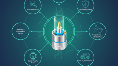
Choosing the right sma male connector is more than matching threads and ordering a familiar part. The connector becomes part of the complete RF path. Its frequency rating, impedance, interface style, cable compatibility, and installation environment all affect performance.
RF engineer and technical writer Steve Arar offers a useful principle: “Every connection is part of the circuit.” That idea deserves attention. A connector can look perfect on a workbench, yet produce signal loss after repeated mating, vibration, or poor cable preparation. Small details matter. Check whether the design uses a 50-ohm interface. Confirm the correct SMA polarity. Review the cable diameter, center-contact size, and required crimp or solder method.
A supplier’s datasheet should show insertion loss, return loss, operating frequency, durability, and material specifications. Look for clear test conditions. Marketing language alone is not enough. Gold-plated contacts may improve corrosion resistance, but plating does not repair a weak mechanical design. That shortcut fails more often than expected.
Environmental conditions also deserve attention. Outdoor equipment may need sealing, stronger strain relief, or a corrosion-resistant body. Laboratory equipment may prioritize repeated mating cycles and stable calibration. A right-angle sma male connector can save space, but it may introduce tighter bend requirements.
The easiest choice is rarely the safest choice. I would compare at least two qualified parts before deciding. One overlooked detail can become a costly field failure. A careful selection process protects signal quality, equipment reliability, and long-term maintenance.
How to Choose the Right SMA Male Connector?
SMA male connector basics begin with the interface, not the appearance. An SMA male connector uses external threads and a center pin for a secure 50-ohm connection. IEC 61169-15 provides dimensional guidance for this connector family. Check the mating interface, frequency range, and cable size before ordering.
A 2024 MarketsandMarkets report estimated steady growth in the global RF connector market through 2030, driven by wireless infrastructure, test equipment, and aerospace electronics. That growth increases selection pressure. For high-frequency circuits, choose a connector with a suitable operating range, low insertion loss, and controlled VSWR. A common target is 1.3:1 or lower, but the complete assembly matters more than the connector alone. Cable quality, crimp accuracy, and launch geometry can change the result.
Small details matter.
During practical assembly, I have seen a visually perfect connector fail because the center pin sat slightly too deep. Use the manufacturer’s recommended stripping dimensions, even when they feel overly precise. Select nickel-plated bodies for general environments and corrosion-resistant finishes for demanding conditions. Avoid mixing incompatible cable types. A right-angle connector may save space, yet it can introduce extra loss and mechanical stress. Torque also deserves attention. Under-tightening causes intermittent contact; over-tightening can damage threads. These choices seem minor, but field measurements often prove otherwise. Check the datasheet, inspect the cross-section, and test the finished cable with a calibrated network analyzer.
Identify the connector type before comparing prices. A standard SMA male connector usually has a center pin and a 1/4-36 UNS threaded coupling nut. Reverse-polarity SMA changes the pin and socket arrangement, even when the shell looks identical. This small difference can stop a correct-looking assembly from mating. Check the equipment drawing, not only the product photograph. I have seen installation errors begin with that shortcut.
Next, confirm the interface requirements. A cable connector may use crimp, clamp, or solder attachment, while a PCB version may require a vertical or edge-mount footprint. Keep the system at 50 ohms, and verify the operating frequency, insertion loss, voltage standing wave ratio, and mating cycles.
A 2024 MarketsandMarkets forecast estimates the global RF connector market will grow from about USD 3.1 billion in 2023 to USD 4.3 billion by 2028. That growth reflects more compact, high-frequency equipment, where small interface errors become measurable losses. Tiny details matter.
Thread compatibility deserves a physical check. Measure the thread standard and inspect the cable diameter before ordering. An SMA male connector for a 2.8 mm cable may not suit a 5 mm cable assembly. Also confirm panel thickness, keying, and environmental sealing.
The IEC 61169-15 specification provides useful dimensional and performance guidance for SMA interfaces, but drawings still need careful review.
I would recheck the mating gender twice. It is easy to confuse shell gender with contact gender.
Choosing the right SMA male connector starts with frequency, not appearance. The SMA interface is commonly rated at 50 ohms, but its usable frequency depends on construction, cable, and assembly quality. Confirm the connector’s upper limit against your operating band. 3GPP TS 38.104 defines FR1 from 410 MHz to 7.125 GHz, while newer FR2 ranges extend from 24.25 GHz to 71 GHz. An ordinary SMA connector may not suit millimeter-wave work.
Impedance matching is equally important. A 50-ohm connector should connect to 50-ohm cables, antennas, and test equipment. Otherwise, reflections waste power and distort measurements. Check return loss, VSWR, and insertion loss in the electrical specification. A return loss of 20 dB equals approximately 1.22:1 VSWR. That is a useful practical target for many RF assemblies, but not every application needs the same margin.
Measure the assembly, not only the connector. Use a calibrated vector network analyzer and inspect the complete signal path. The ITU-R M.2412-0 report identifies candidate IMT-2020 spectrum up to 86 GHz, reminding engineers that frequency demands continue rising. I once selected a connector by its advertised frequency alone. The assembled cable performed worse because torque and stripping length were incorrect. That mistake still matters. Mechanical fit, plating, power rating, and environmental sealing deserve equal attention. A perfect datasheet cannot rescue poor installation.
How to Choose the Right SMA Male Connector?
Choose the Right Cable, Contact Style, and Installation Method
Start with the cable, not the connector. Most SMA systems use 50-ohm coaxial cable, but diameter, shielding, and bend radius still matter. A thin cable suits compact wireless equipment, while a thicker cable usually reduces loss over longer runs. The 2024 Ericsson Mobility Report recorded about 2.3 billion 5G subscriptions worldwide, increasing demand for reliable, high-frequency connections. More signals also expose poor cable choices faster.
Match the contact style to the application. Crimp contacts support faster field installation and consistent production results. Solder contacts can offer strong electrical continuity, but they require controlled heat and careful preparation. For outdoor equipment, check the connector’s sealing design and cable jacket compatibility. IEC 61169-1 provides general requirements for radio-frequency connectors, while MIL-STD-348 defines interface dimensions for several RF connector types. Standards help, but they do not replace the cable manufacturer’s instructions.
Installation quality often decides performance. Strip the jacket evenly, avoid damaged braid strands, and keep the center conductor straight. Use a calibrated torque wrench when tightening the coupling nut; the correct value depends on the connector specification. Do not twist the cable during assembly. I have seen a connector pass a basic continuity test and still fail at high frequency because the braid was uneven. That mistake is easy to repeat. Inspect twice. Measure return loss when the application is sensitive to signal reflection.
Cable diameter, contact style, and installation method must match. The chart compares typical coaxial cable dimensions commonly used with SMA male connectors.
Choosing an SMA male connector starts with materials, not appearance. Brass bodies are economical, while stainless steel better resists moisture, vibration, and repeated handling. Plating also matters. Gold-plated contacts support stable conductivity, but the base metal and plating thickness still require verification. According to Bishop & Associates’ 2024 connector industry report, global connector sales reached roughly 84 billion dollars in 2023. That scale reflects a crowded market, not identical performance. Small differences can matter.
Check the environmental rating against the installation site. IEC 60529 defines IP protection levels, but an IP rating does not automatically prove chemical or salt-spray resistance. For outdoor equipment, review operating temperature, humidity, UV exposure, and corrosion testing. IEC 60068 environmental test methods can help confirm performance under damp heat, vibration, and salt mist. A connector beside a rooftop antenna may face condensation at dawn and thermal cycling by noon. Sealing alone is not enough.
Compatibility requires more than matching SMA threads. Confirm 50-ohm impedance, operating frequency, cable diameter, contact style, and mounting dimensions. Check whether the connector suits RG coaxial cable or the intended PCB footprint. Compare the connector’s mating cycles and torque requirements with the actual service schedule. A wrench can damage the interface when torque values are ignored. I have seen visually identical parts fail because their cable crimp range differed. That detail is easy to miss.
| Selection Dimension | Typical SMA Male Connector Data | What to Verify Before Purchase | Why It Matters |
|---|---|---|---|
| Connector Interface | SMA male, threaded coupling, 1/4-36 UNEF thread | Confirm that the mating connector is SMA female and uses the same interface standard. | Prevents mechanical mismatch, cross-threading, and unreliable mating. |
| Characteristic Impedance | 50 ohms | Check that the cable, antenna, adapter, and equipment are all designed for 50-ohm systems. | A mismatch can increase reflections, insertion loss, and signal distortion. |
| Frequency Capability | Common designs operate from DC to 6 GHz, 12 GHz, or 18 GHz; precision versions may support higher frequencies. | Select a rated frequency range above the highest operating frequency and review the VSWR specification. | Connector geometry and assembly quality strongly affect high-frequency performance. |
| Center Contact Material | Typically brass or beryllium copper, often with gold plating. | Verify base material, plating thickness, contact resistance, and suitability for the expected mating cycles. | The center contact affects conductivity, spring performance, corrosion resistance, and durability. |
| Body Material and Finish | Common body materials include brass or stainless steel; finishes may include nickel or gold plating. | Match the finish to corrosion exposure, mechanical wear, conductivity, and installation requirements. | Material and finish influence strength, corrosion resistance, and long-term electrical stability. |
| Insulator Material | PTFE is widely used in SMA connectors; high-temperature designs may use alternative dielectric materials. | Check the dielectric temperature range and electrical specifications at the intended frequency. | The insulator affects dielectric loss, impedance stability, and temperature capability. |
| Operating Temperature | Many commercial designs are rated approximately from -55°C to +85°C; extended-temperature versions may reach about +125°C or higher. | Compare the complete operating and storage temperature ratings with the actual environment. | Temperature extremes can change contact force, sealing performance, and RF characteristics. |
| Environmental Protection | Unsealed versions are intended for protected indoor use; sealed versions may provide an IP-rated interface when properly mated. | Confirm the exact IP rating, sealing method, cable assembly, and whether the rating applies only when mated. | Moisture, dust, salt spray, and condensation can cause corrosion or impedance changes. |
| Cable Compatibility | Available for coaxial cables with different diameters, including flexible, semi-rigid, and conformable cable types. | Match the connector to cable type, outer diameter, dielectric diameter, center conductor size, and attachment method. | An incorrect cable interface can cause poor retention, high VSWR, or damage during assembly. |
| Termination Method | Common options include crimp, solder, clamp, and PCB or panel-mount configurations. | Confirm required tooling, assembly dimensions, soldering temperature, and installation instructions. | The correct termination method improves repeatability, mechanical strength, and RF performance. |
| VSWR and Insertion Loss | Values vary by design and frequency; high-performance versions may specify VSWR around 1.20:1 or lower over a defined band. | Review the complete test frequency, maximum VSWR, insertion loss, and measurement conditions. | These parameters indicate how much signal is reflected or lost through the connector. |
| Power and Voltage Rating | Ratings depend on frequency, altitude, temperature, cable type, and connector construction; many standard parts are rated in the hundreds of volts DC. | Use the manufacturer’s derating curve and verify peak voltage, RMS voltage, and RF power requirements. | Exceeding the rating may cause arcing, overheating, dielectric breakdown, or permanent damage. |
| Mating and Installation Torque | SMA threaded connections commonly require controlled torque; the exact value depends on the applicable specification and connector design. | Follow the connector datasheet and use a calibrated torque wrench for critical RF assemblies. | Under-tightening can cause intermittent contact, while over-tightening can damage the threads or dielectric. |
| Compliance and Documentation | Relevant documentation may include dimensional drawings, material declarations, test reports, and applicable connector specifications. | Request a current datasheet, dimensional drawing, inspection criteria, and traceable test information. | Complete documentation helps confirm interchangeability, quality, and suitability for regulated applications. |