Skip to content

How to Choose the Right Expulsion Fuses?

Choosing the right Expulsion Fuses starts with understanding the equipment they protect and the faults they must interrupt. These devices are commonly used in overhead distribution systems, including transformer and feeder applications. The correct choice can help limit equipment damage and support reliable service. A poor match may cause nuisance operation or fail to coordinate with upstream protection.

Start with the system voltage, expected load current, and available fault current at the installation point. Then check the fuse’s voltage rating, continuous-current rating, and interrupting capability against the equipment data and manufacturer guidance. Transformer applications need particular care. Inrush current and cold-load pickup can affect fuse-link selection, so a rating chosen from normal load alone may be misleading. Coordination matters, too: the fuse should operate appropriately alongside other protective devices, not simply carry the expected current.

Field conditions deserve attention. A coastal pole with salt exposure, a windy rural line, and a sheltered substation may present different service demands. Confirm that the fuse link and cutout are compatible, and consider local temperature, contamination, and maintenance access. Small details count. No single fuse size fits every installation, and product labels can be easy to misread. Review current manufacturer specifications and applicable engineering requirements, then have a qualified professional verify the selection. This guide outlines the key checks and trade-offs. Some choices still require judgment, and that judgment should be documented rather than guessed.
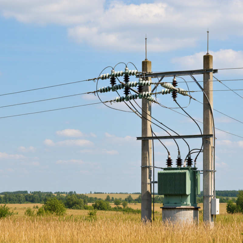
How to Choose the Right Expulsion Fuses?

How Expulsion Fuses Interrupt Fault Currents

How to Choose the Right Expulsion Fuses?

How Expulsion Fuses Interrupt Fault Currents

When a fault drives current beyond a fuse link’s designed limit, the link melts and an arc forms inside the fuse tube. Heat from the arc reacts with the tube’s lining, producing gas that helps cool and deionize the arc. At an AC current zero, the arc can extinguish, stopping current flow. The expelled gases are hot, so installation clearances and equipment orientation matter. The process is fast, but not magic.

IEEE C37.41-2016 sets design-test requirements for high-voltage fuses and cutouts; IEEE C37.48 provides application guidance. Use the site’s short-circuit study to check that the fuse’s interrupting rating meets or exceeds available fault current. Then compare its time-current curve with downstream and upstream protection. There is no single clearing-time figure that suits every fuse: performance depends on fuse-link design, fault magnitude, and system voltage.

Tips: Confirm the fuse’s voltage and interrupting ratings against system data, then review its coordination curve. Check the manufacturer’s published test data and required clearances. A detail easy to miss: the fuse may interrupt correctly yet still disrupt coordination with neighboring devices. Recheck the assumptions when network conditions change.

How to Choose the Right Expulsion Fuses? — How Expulsion Fuses Interrupt Fault Currents

This conceptual, normalized profile illustrates the sequence: fault current rises, the fuse link melts and an arc forms, then gases generated inside the fuse tube help extinguish the arc as current reaches zero. The values are illustrative—not measured data or equipment ratings. Select a fuse using the system voltage, required interrupting rating, load and inrush currents, and coordination with upstream and downstream protection; consult the manufacturer's published specifications.

Assessing System Voltage and Current Requirements

Assessing System Voltage and Current Requirements

Start with the circuit’s highest expected operating voltage, not just its nominal label. A 12.47 kV feeder, for example, may use a 15.5 kV-class fuse, subject to the equipment’s ratings and local coordination practice. Check grounding, available fault current, and the fuse’s interrupting rating too. IEC 60282-2 covers expulsion fuses for AC systems above 1 kV; its scope is useful, but it cannot replace a site-specific study.

Current selection needs more than the transformer’s nameplate load. A 500 kVA, three-phase transformer on a 12.47 kV system draws about 23 A at full load, calculated using the standard three-phase power relationship. That is a load estimate, not a fuse-size recommendation. Account for growth, transformer energization, cold-load pickup, and downstream protection curves. IEEE C37.48-2020 provides application and coordination guidance, while IEEE C37.46-2019 addresses fuse ratings and requirements. Small details matter. A fuse that carries normal current may still operate during inrush, or fail to coordinate with a downstream device. This part is easy to underestimate. Review actual load records and fault-study results; a clean calculation can still rest on a poor assumption.

How to Choose the Right Expulsion Fuses? - Assessing System Voltage and Current Requirements

Assessment dimension Example or check Selection guidance
Nominal system voltage 13.2 kV, 24.9 kV, or 34.5 kV distribution system Confirm the system’s nominal and maximum operating voltage, including grounding and transient conditions.
Fuse cutout voltage class Illustrative pairings: 13.2 kV system with a 15 kV class cutout; 24.9 kV with a 27 kV class; 34.5 kV with a 38 kV class The equipment’s rated maximum voltage must be suitable for the system. Verify the cutout and fuse-link ratings against applicable standards and utility requirements.
Continuous load current For a balanced three-phase load: I = kVA ÷ (√3 × line-to-line kV) Use the expected maximum load, not just the average load. Account for ambient temperature and any equipment derating requirements.
Illustrative load-current calculation 500 kVA at 13.2 kV ≈ 21.9 A; 1,000 kVA at 24.9 kV ≈ 23.2 A; 1,500 kVA at 34.5 kV ≈ 25.1 A These are calculated load currents, not fuse-link recommendations. Select a link using its time-current characteristics and the protected equipment’s requirements.
Fuse-link ampere rating Compare the link’s continuous-current capability with the maximum expected load. Allow for legitimate load growth and temporary loading, but avoid oversizing: an oversized link may not provide the intended protection.
Inrush and temporary current Transformer energization, motor starting, and cold-load pickup can produce short-duration currents above normal load. Check that the fuse-link time-current curve rides through expected inrush without sacrificing fault protection or coordination.
Interrupting capability Determine the available short-circuit current at the installation point. The cutout’s interrupting rating must meet or exceed the available fault current under the applicable test and system conditions.
Protection coordination Review upstream protective devices and downstream equipment protection. Coordinate time-current curves so the intended protective device operates first, while maintaining adequate transformer or line protection.

Note: Voltage-class pairings and load-current calculations above are general screening examples, not a final fuse selection. Confirm the exact cutout and fuse-link ratings, standards, fault duty, coordination, and utility practices with the equipment documentation and a qualified protection engineer.

Selecting Fuse-Link Ratings for the Protected Equipment

How to Choose the Right Expulsion Fuses?
Selecting Fuse-Link Ratings for the Protected Equipment

Choose a fuse-link rating around the equipment’s actual duty, not just its nameplate current. Check rated voltage, continuous load, expected inrush, and the available fault current. For example, a single-phase, 100 kVA transformer on a 13.8 kV primary draws about 7.25 A at full load. That figure is only a starting point. A link chosen too close to load current may operate during energization; an oversized link may not protect the transformer adequately. Real installations are messier.

Compare the fuse’s time-current characteristic with the protected equipment’s withstand limits and upstream and downstream protection. IEEE Std C57.109-2018 provides transformer through-fault withstand curves, relating fault current to allowable duration. IEEE Std C37.48 offers application guidance for distribution fuse links. Use these technical references with the equipment data and a system coordination study, rather than relying on a generic multiplier. Check the curve. Also verify that the fuse can interrupt the maximum fault current at its installation point. Field records can reveal recurring inrush or load changes, but they are not a substitute for calculation. One detail is easy to miss: the nearest standard link rating may not be the best match. Recheck the assumptions before specifying it.

Checking Fault Levels and Coordination with Other Devices

How to Choose the Right Expulsion Fuses?

Checking Fault Levels and Coordination with Other Devices

Start with the maximum available fault current at the fuse location, not just the expected load. Compare this value with the fuse’s interrupting rating under the actual system voltage and installation conditions. Check minimum fault current too: a distant or resistive fault may produce too little current for prompt operation. Review the one-line diagram, transformer data, and utility fault information. Allow for planned network changes; a value that works today may not remain adequate. Real installations are rarely as tidy as drawings suggest.

Coordination matters. Plot the fuse’s minimum-melting and total-clearing curves against those of upstream and downstream devices. The curves should provide a practical operating margin across likely fault levels, while avoiding unnecessary outages for faults beyond the protected section. Include transformer inrush and expected load changes when reviewing the fuse link. A neat curve match can still fail if assumptions about fault current or device tolerances are wrong. Have a qualified protection engineer verify the study and site conditions.

Tips: Record the voltage, maximum and minimum fault current, and adjacent device settings. Check current-time curves at the same voltage base. Keep the assumptions with the coordination study, and revisit them after equipment or network changes.

Verifying Installation Conditions and Safety Requirements

Before choosing an expulsion fuse, verify the actual installation—not just the system’s nominal voltage. Check maximum operating voltage, available fault current, load current, transformer inrush, and the fuse-link time-current curve. Confirm that the fuse’s interrupting rating covers the calculated fault current at its location. IEEE C37.41 describes testing for high-voltage fuse equipment; consult the applicable requirements and the equipment documentation for the specific assembly.

Site conditions matter. Check ambient temperature, altitude, moisture, salt or industrial contamination, mounting orientation, clearances, and enclosure ventilation. Confirm the cutout’s insulation level and that its grounding and disconnect arrangements match the installation drawings. A tidy calculation can still overlook a corroded contact or a cramped enclosure. Small details matter.

The NFPA report Electrical Fires found that U.S. fire departments responded to an estimated average of 32,620 home structure fires involving electrical failure or malfunction each year from 2015 to 2019. Those fires caused an average of 425 deaths, 1,375 injuries, and $1.5 billion in direct property damage annually. The figures cover homes, not utility equipment, but they underline why inspection and condition checks deserve attention. Record the verified ratings, site measurements, and coordination assumptions; have a qualified electrical professional review any uncertainty before installation.