Skip to content

What Is Cable and Wire Harness Assembly?

Cable and wire harness assembly combines wires, terminals, connectors, and protective materials into an organized electrical system. A cable may carry power or signals, while a harness groups and routes multiple connections for a specific application. The terms sometimes overlap, so the exact meaning depends on the product and industry. Details matter.

A typical assembly begins with drawings and material specifications. Technicians cut wires to length, strip insulation, attach terminals, and fit components such as sleeves, labels, or braided coverings. They then arrange the connections and secure them with clips, ties, or protective conduit. A finished harness may look simple, but each branch and connector must match its intended location. Small errors can complicate installation or affect electrical performance.

This article explains what cable and wire harness assembly involves, how its main production steps work, and where these assemblies are used. It also examines design choices, testing, and quality checks. Continuity tests can reveal an open connection, while visual inspection may catch damaged insulation or misplaced labels. However, a passing test does not make every design ideal. Tight bends, difficult access, and unclear documentation can still create problems in the field. A useful overview should cover both the controlled production process and these practical limitations, helping readers ask better questions when specifying or evaluating an assembly.
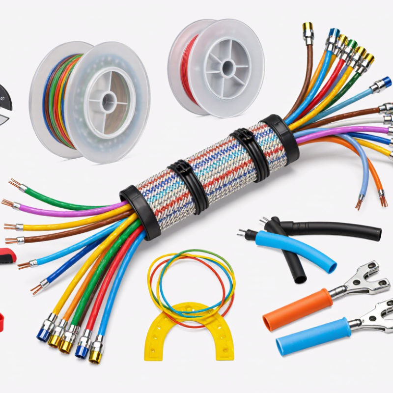
What Is Cable and Wire Harness Assembly?

Defining Cable and Wire Harness Assembly

Cable and wire harness assembly is the controlled process of preparing conductors for reliable use in equipment. A cable assembly usually combines one or more insulated conductors with connectors, shielding, labels, and protective sleeving. A wire harness groups multiple wires into an organized route, often with clips, seals, terminals, and branch points. That distinction is useful, but not absolute.

In practical assembly work, technicians begin with drawings, wire lists, and connector specifications. They cut wires to measured lengths, remove insulation carefully, and attach terminals with calibrated tools. A small crimp error can create heat, signal loss, or an intermittent connection. Details matter. Technicians also check routing, bend radius, polarity, and strain relief before final testing. Continuity testing confirms electrical paths, while visual inspection can reveal damaged insulation or incomplete locks.

Reliable assembly depends on repeatable methods and clear records. Each wire should match its identification mark and intended position. Protective sleeving must cover exposed areas without restricting movement. The boundary between a cable and harness can remain unclear in complex equipment. A drawing may look complete yet miss a service loop or an awkward access point. That is why experienced technicians review the physical sample, not only the documentation. Fit can fail. Feedback from production should update future designs, even when the original plan seemed technically correct.

What Is Cable and Wire Harness Assembly?

A cable or wire harness assembly groups conductors with terminals, connectors, and protective materials to route electrical power or signals. The chart shows an illustrative component count for one representative harness; actual counts vary by design and application.

Key Components and Their Functions

A cable and wire harness assembly organizes conductors into a routed, protected system. Each part has a practical job. Wires carry power or signals, while terminals create electrical contact at connection points. Connectors allow components to be joined or separated during installation and service. Insulation limits unintended contact; braided sleeves, conduit, or tape help guard against abrasion, heat, and movement. In a vehicle, for example, a harness may run behind a dashboard, where sharp edges and tight bends make routing important.

Clips, grommets, and strain reliefs keep the assembly in place and reduce stress near connectors. Labels support identification during installation and repair. IPC/WHMA-A-620 provides industry workmanship criteria for cable and wire harness assemblies, including inspection of crimps, soldered connections, and protective coverings. Grand View Research estimated the global wiring harness market at USD 90.89 billion in 2023, reflecting the scale of systems built from these connected parts. Market size alone, however, does not tell you whether a specific assembly is reliable.

Tips

Check that terminals match the wire size, and inspect crimps for uniform compression. Keep bend radii gentle, especially near connector backshells. A small routing shortcut may look harmless on a bench, but vibration can expose the weakness later. Labels help, though they can still be misplaced.

How Cable and Wire Harnesses Are Designed and Built

What Is Cable and Wire Harness Assembly?

How Cable and Wire Harnesses Are Designed and Built

Design begins with the job the assembly must perform. Engineers identify signal or power needs, operating temperature, movement, and available space. They then select conductors, insulation, shielding, connectors, and protective coverings to suit those conditions. A cable routed beside a warm motor, for example, may need different materials from one inside a stationary control cabinet.

Next, designers turn requirements into drawings, wiring diagrams, and a bill of materials. Each wire needs a defined color, gauge, length, and termination. Connector pin assignments matter too. A clear drawing helps prevent crossed wires and misplaced terminals, but it cannot reveal every installation problem. A bend may be tighter than expected. That detail is easy to miss.

During assembly, technicians cut wires to length, strip insulation, crimp terminals, and insert them into connector housings. They may bundle wires with ties or sleeves, then secure the harness to a fixture that matches its intended shape. Crimp height and pull strength can be checked with suitable tools. Continuity tests verify electrical paths, while visual inspection can catch damaged insulation or incomplete connector locks. Small defects matter. Still, inspection is not a substitute for sound design. Prototypes and production feedback often reveal awkward routing or unclear instructions, and those findings should lead to practical revisions.

Common Assembly Types and Their Applications

What Is Cable and Wire Harness Assembly?
Common Assembly Types and Their Applications

Cable assemblies group insulated wires into a defined route, often with connectors at one or both ends. They suit equipment that needs a flexible, serviceable connection, such as test instruments, control panels, and movable machinery. A short cable with molded strain relief can handle repeated movement better than loose wires. Still, the right construction depends on bend radius, heat, vibration, and cleaning conditions.

Wire harnesses bundle several wires into an organized branch pattern. Tapes, clips, sleeves, or ties hold the conductors in place, while labels help technicians identify circuits during installation. Vehicle bodies, industrial machines, and appliances commonly use harnesses to connect many components without leaving wires tangled across the frame. They can be built on a board that marks each branch and connector position. Small routing changes matter; a harness that fits one prototype may rub against an edge in production.

Some applications need more specialized assemblies. Coaxial cables carry high-frequency signals in communication and measurement equipment, while shielded cables help limit electrical noise near motors or sensitive sensors. Ribbon cables work well for compact, parallel connections inside electronics, but they are not ideal for every moving assembly. Selection should follow the actual load, environment, and maintenance plan—not just the neatest drawing. A practical detail, perhaps overlooked, is leaving enough service length for access without creating loose loops.

Testing and Quality Requirements

Testing and Quality Requirements

A cable and wire harness can look flawless and still contain a hidden fault. Testing checks whether each assembly matches its drawing, materials, and intended operating conditions. The exact test plan depends on the application. Not every harness needs every test.

Continuity testing confirms that each conductor reaches the correct terminal. A technician may use a pin map to catch crossed wires or open circuits. Insulation resistance testing checks for unwanted current paths between conductors. For assemblies exposed to higher voltages, a dielectric withstand test may also be specified. Test levels and acceptance limits should come from the product requirements, not guesswork.

Mechanical checks matter, too. Pull testing can reveal a weak crimp, while a close visual inspection may catch damaged insulation, loose seals, or an incorrectly seated connector. Small details count. Records should identify the assembly, test results, equipment, and any rework performed. This makes recurring faults easier to trace across production batches.

A passing electrical test does not prove that a harness will survive vibration, heat, or repeated bending. Those risks may call for application-specific checks or sample testing. There is a gap here: inspection cannot predict every failure. Reviewing field feedback and updating test plans helps narrow it. It is not perfect, but ignoring that feedback is worse.

What Is Cable and Wire Harness Assembly? - Testing and Quality Requirements

Test or Quality Dimension What It Verifies Typical Inspection or Test Method Acceptance Requirement When It Is Applied
Visual workmanship Correct wire colors, routing, labels, connector orientation, seals, and overall assembly condition. Visual inspection against the drawing, bill of materials, and approved workmanship criteria. No missing or incorrect parts, visible conductor damage, loose strands, misplaced seals, or unapproved workmanship defects. Incoming inspection, in-process checks, and final inspection.
Electrical continuity and circuit mapping That each intended circuit is electrically connected and assigned to the correct connector cavities. Automated or manual point-to-point testing with a harness test fixture. Every specified connection passes; unintended opens, shorts, and miswires are not permitted. Resistance limits are defined by the design and test setup. Typically tested on every completed harness.
Contact and conductor resistance That a circuit has sufficiently low resistance for its specified current and signal requirements. Four-wire (Kelvin) measurement for low-resistance circuits, or a suitable calibrated resistance meter. Must meet the drawing or product specification, accounting for conductor length, wire size, contacts, and measurement-lead compensation. Production validation, process audits, and qualification testing.
Insulation resistance Electrical isolation between conductors and, where applicable, between conductors and a shield or chassis. Insulation-resistance meter at the test voltage specified for the product; sensitive components may need to be disconnected or protected. Must meet the project-defined minimum. Test voltage and limit depend on the assembly’s design and applicable requirements. As specified by the test plan; commonly included in electrical qualification or production testing.
Dielectric withstand (hi-pot) Ability of insulation to withstand a specified voltage without breakdown or excessive leakage. Apply the prescribed AC or DC test voltage between the specified isolated circuits for the defined duration. Voltage, duration, leakage limit, and test points must follow the approved product specification or applicable standard; do not apply where connected components could be damaged. Design qualification or production testing when required by the product specification.
Crimp height and crimp appearance That a crimped terminal has been formed consistently and has no visible defects such as cracked wings or trapped insulation in the conductor area. Measure crimp height with a suitable gauge or micrometer; inspect crimp geometry and wire placement. Crimp dimensions and appearance must conform to the terminal and wire-application requirements. First-piece approval, setup checks, and periodic process monitoring.
Crimp pull-force test Mechanical strength of the wire-to-terminal crimp. Pull the wire and terminal axially using a calibrated tensile tester at the method and rate defined by the applicable requirement. Minimum force depends on wire size, conductor construction, terminal design, and the governing specification; record the measured force and failure mode. Process qualification, tooling changes, and scheduled production audits.
Crimp cross-section analysis Internal crimp formation, including conductor compression, strand distribution, and potential voids or damage. Prepare, polish, and examine a crimp cross-section under magnification using defined inspection criteria. Conductor and terminal features must meet the approved crimp-application criteria; limits are specific to the terminal and wire combination. New-process qualification, troubleshooting, and periodic validation.
Connector retention and locking That terminals are fully seated and connector locks, secondary locks, and latches function as intended. Visual and tactile inspection, terminal push-back checks, and retention-force testing where specified. Terminals must not back out under the specified check; retention force and connector operation must meet the product requirements. In-process assembly checks and final inspection.
Dimensions and branch locations That overall length, breakout positions, branch lengths, and connector locations fit the intended installation. Measure the harness in the drawing’s defined layout or inspection fixture. Measured dimensions must remain within the tolerances on the approved drawing. First-article inspection and production sampling or inspection as specified.
Label and traceability verification Correct part identification, revision, circuit marking, and production traceability. Compare labels and production records with the released assembly documentation. Required information must be legible, accurate, correctly positioned, and traceable to the applicable production records. Final inspection and packaging release.
Environmental and durability testing Performance after exposure to relevant temperature, humidity, vibration, fluid, or flex conditions. Test representative assemblies using the environmental profiles and procedures defined for the end-use application. After testing, the harness must meet specified electrical, mechanical, and visual requirements; exposure limits are application-specific. Product qualification, design changes, or customer-required validation.

Note: Acceptance limits are not universal. Use the released drawing, product specification, applicable standards, and approved test plan to set test voltages, force limits, dimensions, and pass/fail criteria.