Skip to content

What Are Wire Assemblies and How Are They Used?

Wire assemblies quietly power the systems people depend on every day. They connect sensors, switches, batteries, motors, and control units inside vehicles, medical devices, appliances, and industrial equipment. A finished assembly may look simple, yet its performance depends on accurate cutting, stripping, crimping, routing, and testing.

Industry engineer Steve Lampert explains, “A wire assembly is only as reliable as its weakest termination.” This practical warning deserves attention. One loose crimp can create heat, signal loss, intermittent operation, or complete failure. In a factory, that fault might appear as a flashing warning light. Inside medical equipment, the consequences could be far more serious.

This article examines what wire assemblies are and how manufacturers use them. It will explore their basic parts, including conductors, insulation, terminals, connectors, sleeving, and protective coverings. It will also describe how custom assemblies improve installation speed, reduce wiring errors, and simplify maintenance.

Details matter.

Wire size affects current capacity. Insulation affects temperature resistance. Connector choice affects durability and service access. Manufacturing experience helps, but it does not remove uncertainty. A design that performs well in a laboratory may struggle near vibration, moisture, chemicals, or repeated bending.

The discussion will therefore remain practical and evidence-minded. It will consider both the strengths and limitations of wire assemblies. Readers will see why correct specifications, controlled workmanship, and documented testing matter before production begins.
What Are Wire Assemblies and How Are They Used?

Definition and Core Components of Wire Assemblies

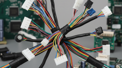
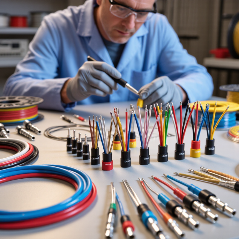
A wire assembly is a prepared group of wires built for a specific electrical connection. It combines insulated conductors, terminals, connectors, and protective materials into one organized unit. Unlike loose wiring, an assembly arrives cut, arranged, and terminated for installation. Its purpose is simple: carry power or signals safely between components. Small details matter.

Core components include conductors, insulation, terminals, connectors, and protective coverings. Copper is common because it offers strong conductivity and practical flexibility. Insulation separates each conductor and helps resist heat, moisture, abrasion, and electrical contact. Terminals or connectors create secure attachment points at both ends. A protective sheath can bundle wires together and reduce movement during operation. Labels, seals, clips, and strain reliefs may also support identification and durability.

In equipment, wire assemblies connect sensors, control boards, motors, lighting units, and power sources. A well-designed assembly reduces installation time and limits wiring errors. Manufacturers typically verify continuity, resistance, terminal retention, and insulation condition. Visual inspection still matters. A wire may pass an electrical test yet show poor routing or weak support. A first design can look correct, but a tight bend may damage it over time. The required bend radius deserves careful attention. Connectors must match the circuit, environment, and expected vibration. Designs sometimes need revision after testing. That is not failure. It is useful evidence.

Wire Assemblies: Conductor Resistance by Cross-Sectional Area

Definition and core component context: the conductor is the current-carrying element inside a wire assembly.

This chart shows the calculated resistance of copper conductors over 100 meters at 20°C. Values are based on copper resistivity of approximately 0.01724 Ω·mm²/m. Larger conductor cross-sectional areas have lower resistance, which generally makes them more suitable for higher-current power connections. A complete wire assembly may also include insulation, terminals, seals, shielding, protective sleeving, and identification features.

How Wire Assemblies Are Designed and Manufactured

What Are Wire Assemblies and How Are They Used?

Wire assemblies are engineered electrical pathways, not simply bundled cables. A typical assembly includes conductors, insulation, terminals, seals, labels, and protective sleeving. Designers begin with current, voltage, temperature, vibration, and installation space. They also check bend radius and connector orientation. A few millimeters can decide whether a harness fits behind a panel.

A 2024 Grand View Research report estimated the global wire harness market at about $90.45 billion in 2023. It also projected a 6.3% annual growth rate through 2030. This expansion increases pressure on design accuracy and production traceability. Engineers usually select wire gauge through load calculations, then verify crimp geometry with cross-section analysis and pull testing. The IPC/WHMA-A-620 standard provides widely used acceptance guidance for workmanship, terminals, and cable assemblies.

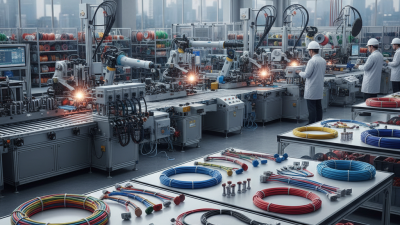
Manufacturing starts with cutting, stripping, marking, and terminal crimping. Automated equipment improves repeatability, but it cannot replace process checks. Operators inspect conductor strands, insulation damage, locking features, and seal placement. Electrical tests may include continuity, resistance, and dielectric withstand testing. A 2023 automotive wiring harness report from Fortune Business Insights identified vehicle electrification as a major demand driver. Higher voltage systems create stricter insulation and routing requirements. A practical warning remains important: a drawing can be correct and still produce a poor assembly. Tight bends, unclear labels, or weak strain relief often appear only during installation. That feedback should return to the design team.

Types of Wire Assemblies and Their Key Differences

What Are Wire Assemblies and How Are They Used?

Types of Wire Assemblies and Their Key Differences

Wire assemblies combine conductors, terminals, insulation, and protective coverings into a tested electrical pathway. They transfer power or signals between components in vehicles, control panels, appliances, and industrial equipment. Unlike loose wires, an assembly arrives cut, arranged, terminated, and often labeled for installation. This reduces wiring time and helps prevent connection errors during production and maintenance.

A wire harness groups several wires inside sleeves, conduits, or braided protection. It suits complex systems with many branches and connection points. A cable assembly usually contains one or several cables with connectors at each end. It is easier to replace as a complete unit. Ribbon cables use parallel conductors and fit compact digital equipment. Coaxial assemblies use layered shielding and controlled geometry for high-frequency signals. Small spaces favor them. Overmolded assemblies add molded protection around a connector or joint, improving resistance to moisture, vibration, and pulling forces.

The key differences involve flexibility, shielding, connector style, environmental protection, and manufacturing cost. A harness may offer excellent organization but require more installation space. A coaxial assembly protects signal quality, yet it may bend less freely. Engineers should check current, voltage, temperature, bend radius, and mating compatibility before selection. Field experience also shows that a tidy assembly can still fail when strain relief is weak. Not every assembly fits. Reviewing failed connections and installation feedback often reveals design assumptions that testing missed.

Common Applications Across Industries

Wire assemblies combine insulated wires, terminals, connectors, protective sleeves, and sometimes shielding into one organized unit. Their purpose is simple: deliver power or signals safely between components. A well-built assembly reduces installation time and prevents loose wires from rubbing against sharp edges. Small details matter.

In vehicles, wire assemblies connect lighting, sensors, control units, and dashboard equipment. They must tolerate vibration, heat, moisture, and repeated movement. In industrial machinery, assemblies route power to motors, switches, and safety controls. Technicians often label each branch for faster maintenance. A misplaced connector can stop an entire production line.

Medical equipment uses compact assemblies for monitors, imaging systems, and patient-support devices. These cables need reliable insulation and careful cleaning compatibility. Aerospace systems demand low weight, secure locking, and resistance to temperature changes. Renewable energy equipment uses assemblies in battery storage, solar inverters, and wind turbine controls. The layout can affect both service time and heat management.

Not every design is perfect. A harness may pass testing but remain awkward to install. Field feedback often reveals this weakness. Engineers can adjust bend length, connector access, or protective coverage before the next production run. In my experience, clear drawings and consistent testing are as important as the materials themselves. A neat assembly is easier to inspect. It is also easier to trust.

What Are Wire Assemblies and How Are They Used? - Common Applications Across Industries

Typical wire assembly applications, construction features, and selection considerations
Industry Typical Wire Assembly Common Function Typical Conductors Important Design Factors Examples of Use
Automotive Vehicle wiring harnesses and sensor leads Distribute power and transmit signals between electrical and electronic systems Copper conductors with PVC, cross-linked polyethylene, or other automotive-grade insulation Vibration, temperature changes, abrasion, moisture, routing space, bend radius, and connector locking Lighting, engine sensors, braking systems, infotainment, battery connections, and body electronics
Aerospace Lightweight shielded cable assemblies and aircraft harnesses Support power distribution, avionics, communications, and control signals Fine-stranded copper or other qualified conductors with lightweight, low-smoke insulation Weight reduction, fire and smoke performance, electromagnetic compatibility, routing security, and traceability Flight instrumentation, cabin systems, navigation equipment, and actuator controls
Industrial Automation Control cables, machine harnesses, and sensor cables Connect programmable controllers, motors, sensors, valves, and operator interfaces Stranded copper conductors, often with twisted pairs, shielding, or flexible jackets Continuous flexing, electrical noise, oil exposure, temperature, ingress protection, and serviceability Robotic equipment, conveyor systems, packaging machinery, and production-line controls
Medical Equipment Patient-monitoring cables, probe leads, and equipment harnesses Carry low-voltage power and measurement signals between sensors, displays, and control units Fine-stranded copper, shielded signal conductors, and flexible medical-grade jackets where required Signal integrity, cleanability, biocompatibility requirements, repeated flexing, insulation integrity, and patient safety Diagnostic monitors, imaging accessories, surgical equipment, and laboratory instruments
Telecommunications Data, coaxial, fiber-optic, and power cable assemblies Transmit data, radio-frequency signals, and electrical power between network equipment Copper pairs, coaxial conductors, or optical fibers depending on the signal type Impedance control, attenuation, shielding, bend radius, connector cleanliness, and environmental sealing Data centers, cellular infrastructure, broadband networks, and switching equipment
Renewable Energy Solar photovoltaic cables, inverter leads, and battery cable assemblies Connect energy-generating modules, storage systems, inverters, and distribution equipment Stranded copper or aluminum conductors with outdoor-rated insulation UV exposure, outdoor temperature range, moisture, current capacity, polarity, and voltage rating Solar arrays, battery storage cabinets, wind-turbine controls, and charging infrastructure
Consumer Electronics Internal lead wires, ribbon cables, and connectorized harnesses Connect circuit boards, displays, batteries, switches, speakers, and sensors Small-gauge copper conductors with compact flexible insulation Compact packaging, low insertion force, signal integrity, heat management, and assembly efficiency Computers, appliances, audio equipment, cameras, and handheld devices
Energy and Utilities Power cable assemblies, control harnesses, and instrumentation cables Carry power and monitoring signals through generation, distribution, and control systems Copper or aluminum conductors, including shielded and multi-core constructions Voltage and current rating, thermal performance, insulation coordination, grounding, and environmental exposure Switchgear, substations, generators, metering systems, and industrial power equipment
Rail Transportation Rolling-stock harnesses, control cables, and door-system assemblies Connect traction, braking, lighting, passenger-information, and control systems Stranded copper conductors with flexible, flame-resistant insulation Vibration, mechanical fatigue, fire performance, electromagnetic compatibility, and maintenance access Passenger rail vehicles, signaling equipment, platform systems, and maintenance machinery
Marine and Offshore Marine power cables, navigation harnesses, and sealed connector assemblies Provide power and signal connections in vessels and offshore equipment Tinned copper or other corrosion-resistant conductors with marine-rated insulation Saltwater corrosion, water ingress, vibration, oil exposure, flame performance, and galvanic compatibility Navigation systems, pumps, propulsion controls, communication equipment, and offshore monitoring
What is a wire assembly? A wire assembly is a prepared electrical interconnect made from one or more wires or cables, terminated with components such as crimp contacts, terminals, plugs, sockets, splices, or protective sleeving. The finished assembly is designed to simplify installation, improve consistency, and provide reliable power or signal connections.

Selection, Testing, Installation, and Maintenance Considerations

Wire assemblies combine conductors, terminals, insulation, and protective coverings into prepared electrical connections. They appear in vehicles, control cabinets, medical equipment, and industrial machines. Selection starts with the actual environment, not the catalog photograph. Confirm current, voltage, temperature, flexing, moisture, chemical exposure, and available space. Match conductor size to the load and allowable voltage drop. Terminal materials and plating also matter where corrosion or vibration is present. A flexible cable may suit a moving arm, while a rigid harness may fit a fixed panel. Small details matter.

Testing should follow a documented inspection and test plan. Check wire routing, strip length, crimp height, terminal position, and labels. A continuity test finds open circuits, but it cannot prove a reliable crimp. Pull testing can verify mechanical strength on sample assemblies. Insulation resistance and dielectric tests help identify damage or inadequate separation. Use calibrated instruments and record results by assembly number. In practice, rushed inspection is tempting. It is also where hidden defects survive. One missed strand can heat under load.

During installation, protect bend zones and respect the minimum bend radius. Do not pull a harness by its terminals. Secure it against abrasion, sharp edges, heat sources, and repeated movement. Leave enough service length for inspection and repair. Maintenance teams should check loosened fasteners, discoloration, cracked insulation, moisture entry, and unexpected resistance changes. Clean connections only with approved methods for the insulation and contact materials. Replace damaged assemblies instead of forcing a temporary repair. Maintenance notes often reveal more than a single test report, although this approach is not perfect; record the failure condition, not merely the replacement date.