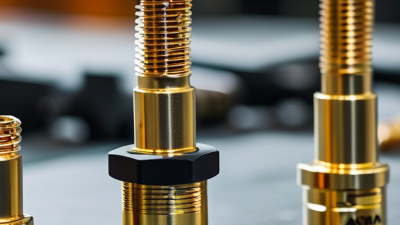
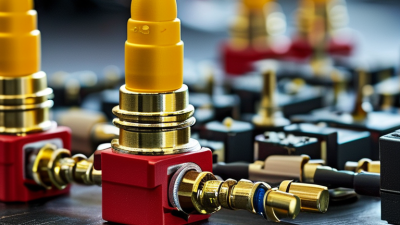
An sma female connector is a compact coaxial interface used to join radio-frequency cables, antennas, and electronic equipment. Its threaded outer body creates a firm mechanical connection. Inside, a center contact carries the signal. A dielectric material separates that contact from the grounded metal shell.
Small, but important.
When an SMA female connector mates with an SMA male plug, the coupling nut tightens around matching threads. This action holds the connection steady and helps maintain consistent electrical contact. Many SMA systems are designed for 50-ohm impedance, supporting applications such as wireless communication, test instruments, GPS devices, and microwave assemblies. However, connector performance depends on more than appearance. Cable type, frequency range, plating, torque, and manufacturing quality can all affect signal loss.
A practical inspection should check the center contact, thread condition, and connector alignment. Dust or a slightly bent pin may create intermittent performance. The manufacturer’s datasheet remains the most reliable reference for torque values and operating limits. It is also important to distinguish standard SMA connectors from reverse-polarity versions. They may look similar, yet their internal interfaces differ.
This guide explains what an SMA female connector is, how its structure supports signal transmission, and where installation mistakes commonly occur. Some explanations simplify complex electromagnetic behavior. That limitation deserves attention. Real-world results should be verified through specifications, careful assembly, and appropriate RF testing.
What Is an SMA Female Connector and How Does It Work?
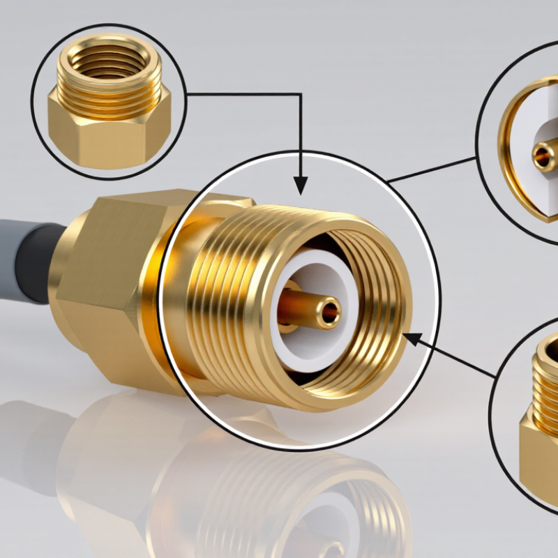
An SMA female connector is a threaded, 50-ohm RF interface for coaxial cables and equipment. Its center contact uses a socket, while the outer body carries internal threads. A male connector screws into it and creates firm mechanical pressure. The structure usually includes a metal body, center contact, dielectric insulator, and threaded coupling section. These parts maintain signal continuity and reduce unwanted movement.
SMA connectors commonly support frequencies up to 18 GHz, although performance depends on design, cable quality, and installation. IEC 61169-15 defines key interface requirements for SMA-type connectors. A 2024 RF connector market report from Grand View Research places projected industry growth in the high-single-digit CAGR range through 2030. That trend reflects rising demand in wireless infrastructure, test equipment, and compact radar systems. Still, higher frequency does not always mean better performance. Small gaps matter.
Tips: Keep the mating surfaces clean and align the threads by hand. Do not force the coupling nut. A torque wrench helps prevent damage and inconsistent measurements. Check the datasheet for return loss, operating frequency, and maximum torque. In practice, one overlooked cable bend can change the result. It is easy to blame the connector first. That assumption deserves checking.
An SMA female connector is a compact coaxial interface used for stable radio-frequency connections. Its center contact is a socket, which receives the pin from an SMA male connector. The outer threaded body provides mechanical retention and forms part of the electrical shield. Inside, a dielectric insulator, commonly PTFE, keeps the center contact aligned while limiting signal loss. Small dimensions matter here. A slight misalignment can affect performance at higher frequencies.
The connector body is usually made from machined brass or stainless steel. Brass is easy to machine, while stainless steel offers stronger threads and better resistance to wear. Contact surfaces may use gold plating because gold resists oxidation and maintains reliable conductivity. Nickel plating can support hardness and surface protection. The center contact is often copper alloy beneath its plating. Some designs include a gasket or seal for moisture resistance, but not every SMA female connector is weatherproof. That detail is easy to miss. Cable versions also use crimp, solder, or compression attachment methods, depending on the installation.
Tips: Check the socket for bending, dust, or uneven plating before connection. Tighten the coupling nut by hand, then use the specified torque when available. Do not rotate the cable while tightening. A connector may look clean yet contain a damaged dielectric. I have found that visual inspection alone is not enough; continuity and return-loss testing provide more dependable evidence. Material choices are practical, not perfect, so match the connector to frequency, cable type, vibration, and environmental conditions.
An SMA female connector secures an RF path through a threaded mechanical interface. Its center contact is a socket. The mating male pin enters it and carries the signal. The outer metal body provides the return path and electromagnetic shielding. Together, these parts maintain a controlled 50-ohm connection.
The coupling nut tightens against matching threads. This creates stable contact pressure and reduces movement during vibration. IEC 61169-15 defines key SMA interface requirements, including dimensions and mechanical performance. A 2024 RF connector market report estimated the sector at about USD 3.8 billion and projected roughly 7% annual growth through 2029. That expansion reflects wider use in test equipment, wireless infrastructure, and satellite systems.
Installation still matters. A technician should inspect the threads, align the connector straight, and apply the specified torque. Overtightening can damage the interface. Finger-tight is not enough. Poor alignment may increase insertion loss or voltage standing wave ratio. In practice, dust and worn threads cause more trouble than many engineers expect. A clean connector can show excellent results at low frequency, yet fail at higher bands. This is why professionals verify performance with a calibrated network analyzer, rather than trusting feel alone. The connection is secure, but never automatically perfect.
| Specification or Feature | Typical SMA Female Connector Data | How It Supports a Secure RF Connection |
|---|---|---|
| Connector Type | Threaded coaxial RF connector with a female center contact | The female interface accepts the mating male center pin while the threaded outer coupling provides mechanical retention. |
| Electrical Impedance | 50 ohms | A controlled 50-ohm geometry helps reduce reflections and maintain predictable signal transfer in RF systems. |
| Typical Frequency Range | DC to 18 GHz for many standard designs | The operating range depends on the connector design, cable, assembly quality, and mating components. Precision versions may support higher frequencies. |
| Coupling Mechanism | 1/4-36 UNEF threaded coupling interface | The fine thread allows the connector halves to be tightened securely, helping prevent accidental separation and intermittent contact caused by vibration. |
| Center Contact | Female socket contact, commonly made from a conductive copper alloy with a plated surface | The socket is designed to receive the mating pin with controlled contact pressure, supporting a stable low-resistance electrical path. |
| Outer Conductor | Continuous conductive shield surrounding the dielectric and center contact | The outer conductor completes the coaxial transmission path and helps contain electromagnetic fields, reducing unwanted radiation and susceptibility to interference. |
| Interface Geometry | Coaxial 50-ohm interface with a PTFE or equivalent dielectric support in many designs | Concentric alignment between the center contact, dielectric, and outer conductor helps preserve impedance continuity across the connection. |
| Typical Body Material | Machined or formed metal body, often with a corrosion-resistant plated finish | A rigid conductive body maintains alignment, provides shielding, and withstands the mechanical force applied during mating and tightening. |
| Panel-Mount Versions | Available with a threaded bulkhead, flange, or solder-mount configuration | Panel mounting fixes the connector to equipment and transfers cable movement away from the internal circuit or RF module. |
| Connection Procedure | Align the male pin, insert straight, and tighten the coupling nut by hand or to the specified torque | Correct alignment prevents damage to the socket and pin. Proper tightening creates consistent mechanical and electrical contact without over-stressing the interface. |
| Typical Insertion Loss | Often below approximately 0.2 dB at lower microwave frequencies for a good-quality connection; actual values vary | Low insertion loss indicates that only a small portion of the RF signal is dissipated at the connector. Cable, frequency, workmanship, and connector condition affect the result. |
| Return Loss | Commonly around 20 dB or better over part of the rated band, depending on design and frequency | Higher return loss generally means less reflected power and a better impedance match. The complete cable assembly determines the measured system value. |
| Environmental Protection | Indoor versions are generally not sealed; weather-resistant versions may use seals or gaskets | A sealed construction helps limit moisture and contaminants that can increase contact resistance, corrosion, and RF mismatch. |
| Common Applications | Test equipment, antennas, wireless modules, navigation equipment, instrumentation, and RF cables | The threaded interface is suitable for applications requiring a compact, repeatable, and mechanically secure coaxial RF connection. |
| Important Installation Practice | Keep the connector clean, avoid side loading, do not rotate the cable during mating, and use the specified torque | These practices protect the center socket, preserve alignment, reduce wear, and help maintain consistent RF performance over repeated connections. |
An SMA female connector is a threaded RF interface with a socket-style center contact. It mates with an SMA male connector and maintains a controlled 50-ohm path. The threaded coupling helps prevent movement during vibration. Small size matters.
Its electrical ratings deserve careful attention. Many SMA designs operate from DC to 18 GHz, while precision versions may reach higher frequencies. The stated range is not a guarantee of identical performance across the band. Return loss, VSWR, insertion loss, and phase stability can change noticeably near the upper limit. Voltage and power ratings also depend on frequency, temperature, and signal type. Continuous high-power signals require more caution than short pulses.
Mechanical details often decide real performance. A clean mating surface reduces unwanted resistance and reflections. The center contact must remain aligned. Excessive torque can deform the interface, while insufficient torque may create intermittent readings. Cable bending near the connector can shift phase and increase loss. In testing, a connector may meet its datasheet rating but still perform poorly after repeated assembly. This is an easy point to overlook. Cable quality, grounding, enclosure design, and calibration also influence results. Use the connector’s actual test conditions when comparing specifications, because published values are not always directly comparable.
What Is an SMA Female Connector and How Does It Work?
An SMA female connector is a threaded RF interface with a center socket. It mates with an SMA male plug, creating a stable 50-ohm signal path. The outer metal body provides shielding, while the dielectric supports the center contact. Proper mating helps reduce signal leakage and reflections. Even a small gap can affect high-frequency performance.
Common SMA female connector types include straight, right-angle, bulkhead, panel-mount, PCB, and cable-mount designs. Straight versions suit open layouts and short cable runs. Right-angle versions save space inside compact enclosures. Bulkhead and panel-mount types pass through a case wall. PCB and edge-launch versions connect directly to circuit boards. Reverse-polarity versions also exist, but they should not be confused with standard SMA interfaces.
These connectors appear in antennas, wireless modules, test instruments, navigation equipment, and industrial sensors. Selection starts with frequency and impedance. Check the connector’s rated frequency, return loss, and power capacity. Match the cable size and dielectric type carefully. Mechanical details matter too: thread style, mounting method, mating cycles, and available clearance. Outdoor equipment may need sealing or corrosion resistance. Use the correct torque rather than excessive force. A common mistake is choosing by shape alone. In practice, connector quality, cable routing, and installation accuracy can matter just as much. I would also verify the datasheet, because frequency ratings are not always directly comparable.
SMA female connectors use a threaded coupling mechanism and a 50-ohm interface to provide a secure connection for coaxial cables, RF equipment, antennas, test instruments, and PCB assemblies.
The chart shows representative upper frequency ratings commonly associated with major SMA female connector configurations. Actual limits depend on connector design, cable type, mounting method, VSWR requirements, and manufacturer specifications. Select the connector according to frequency, impedance, installation method, mating interface, and environmental conditions.