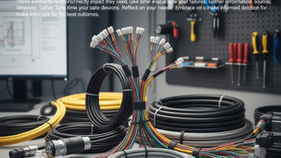
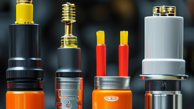
What Are the Top RF Connector Types in 2026?
Choosing an rf connector in 2026 is not just a matter of matching a plug to a cable. Frequency range, impedance, power handling, size, and operating conditions all shape the right choice. A connector that works well inside a test bench may be a poor fit on a vibrating outdoor unit. Small details matter.
This guide compares widely used types, including SMA, BNC, N-type, TNC, F-type, and compact options such as MMCX. Each has trade-offs. SMA connectors are common in compact microwave assemblies, while BNC’s quick bayonet coupling suits many lower-frequency test and video systems. N-type connectors are often selected for larger, robust installations. But these are practical tendencies, not universal rules. Check the manufacturer’s specifications for frequency limits, impedance, mating cycles, and environmental ratings before choosing.
The best option depends on the whole connection path. Cable type, adapter count, installation space, and maintenance access can affect performance as much as the connector itself. A neatly specified connector can still disappoint if it is poorly assembled. That part is easy to underestimate. The sections ahead outline the main connector families, their typical strengths, and the details worth verifying for real applications. Treat any “top” ranking as a starting point, not a substitute for matching the connector to your equipment and conditions.
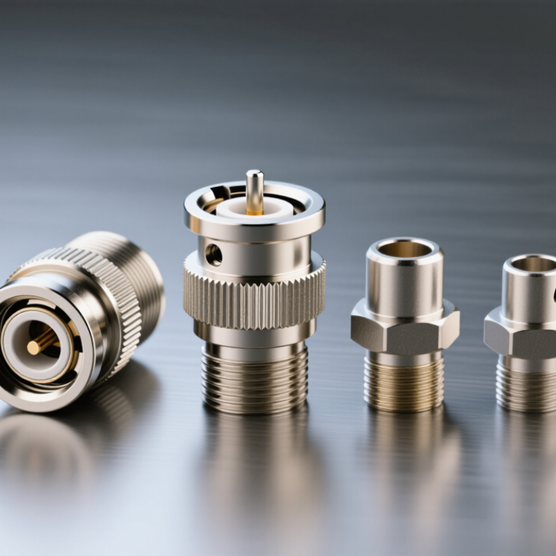
What RF Connectors Do and How They Are Classified
An RF connector joins a coaxial cable to equipment such as an antenna, radio, or test instrument. Its center contact carries the signal, while the surrounding body continues the cable’s shield. Good mating preserves impedance and limits reflections, leakage, and unwanted signal loss. Small details matter. Loose coupling, worn plating, or poorly prepared cable ends can spoil an otherwise sound link. Connector types are classified in several practical ways. Impedance is one: 50-ohm designs are common in radio and test systems, while 75-ohm designs often serve video paths. These values are not freely interchangeable.
Physical interface offers another classification: threaded, bayonet, or push-on coupling. Threaded joints resist loosening; bayonet joints connect quickly; push-on styles favor compact, frequent access. Size and operating frequency matter too. Compact connectors can suit dense panels, but higher frequencies demand tighter manufacturing tolerances and careful cable assembly. Common families include SMA, BNC, N, TNC, SMB, and MCX, each with different dimensions and performance ranges. Do not choose by name alone. Check the equipment interface, cable impedance, frequency range, power level, and expected mating cycles. A datasheet helps, but real installations add bends, vibration, and imperfect handling. Classification charts simplify choices; they cannot predict every field problem.
Which RF Connector Types Stand Out in 2026?
In 2026, SMA, N-type, 2.92 mm, and SMPM connectors stand out for different jobs. SMA remains practical for compact test setups and many RF links below roughly 18 GHz. N-type connectors suit outdoor equipment, where a threaded coupling and larger body support robust connections. Neither is automatically the better choice; cable, frequency, and installation space matter.
For higher-frequency testing, 2.92 mm connectors are commonly specified to 40 GHz, while SMPM designs offer a smaller footprint for dense board-to-board links. Check the exact connector and cable ratings: performance varies by design and assembly. The Q4 2024 5G Americas report, drawing on Omdia data, counted 2.25 billion global 5G connections. That scale helps explain demand for compact, repeatable RF interconnects, but it does not make one connector type universal. Fit matters. In practice, teams can under-document mating cycles, torque, or transition losses; those details may matter as much as the connector’s headline frequency rating.
What Are the Top RF Connector Types in 2026?
Common RF connector interfaces compared by typical upper operating frequency.
Smaller precision interfaces generally support higher frequencies: BNC and N are common in lower-frequency systems, while 2.92 mm, 2.4 mm, and 1.85 mm interfaces are used for microwave and millimeter-wave applications. Values shown are typical nominal limits; actual performance depends on connector design and assembly.
How SMA, BNC, N-Type, TNC, and SMB Connectors Differ
What Are the Top RF Connector Types in 2026?
How SMA, BNC, N-Type, TNC, and SMB Connectors Differ
Choosing an RF connector means balancing frequency, size, vibration, and how often the connection must be made. SMA connectors are compact and threaded; common assemblies are rated to 18 GHz. N-Type connectors are larger, weather-resistant options often rated to 11 GHz. These are typical catalog figures, not universal limits. IEC 61169 specifications define connector interfaces and test requirements, while the complete cable assembly determines real-world performance.
BNC connectors use a quick bayonet lock, making them handy on test benches; many standard versions reach about 4 GHz. TNC keeps a similar profile but uses threads, which help resist loosening under vibration; common versions reach about 11 GHz.
SMB is smaller and snap-on, saving panel space, though many versions are rated near 4 GHz. Check the exact datasheet. Cable type, adapters, and wear can change measured loss and usable bandwidth.
Real life is messier. A connector that fits neatly may still be the wrong choice for repeated handling or outdoor exposure.
Where Leading RF Connector Types Are Commonly Used
SMA connectors are common in compact test equipment, antenna feeds, and microwave modules, where threaded coupling helps resist movement during handling. N-type connectors often suit outdoor antennas, base-station cabling, and other systems needing a sturdier interface. Their larger bodies are less convenient in tight enclosures. BNC connectors appear on oscilloscopes, video equipment, and laboratory cables because their bayonet coupling makes repeated connections quick. Convenient, but not universal. The connector’s rated frequency and cable assembly still need checking.
TNC connectors use a threaded coupling and can be useful where vibration may loosen a bayonet-style connection. SMB and MCX types fit smaller radios, receivers, and embedded devices, though their push-on interfaces require careful handling. U.FL-style miniature connectors are found inside compact wireless products, linking circuit boards to small antenna leads. They save space, but repeated mating can be unforgiving. I have seen connector choice treated as a minor detail; it is not. A poor fit, damaged center contact, or mismatched cable can increase signal loss or create inconsistent measurements. Select by frequency range, power needs, environment, and how often the connection will be handled. Ratings vary by exact design.
How to Choose an RF Connector for Frequency, Power, and Environment
In 2026, common RF connector choices include SMA, BNC, N-type, TNC, and SMP. The right option depends on more than its name. Check the connector’s rated frequency against the highest signal frequency in your system, with room for measurement uncertainty. A connector that fits physically may still create mismatch loss or unwanted reflections. Fit is not enough.
Power handling changes with frequency, cable type, and operating conditions. Review the manufacturer’s specifications for your exact connector and assembly, rather than relying on a general connector-family limit. For outdoor or mobile equipment, consider sealing, vibration, temperature swings, and corrosion. A threaded interface can resist loosening, while a quick-connect design may suit frequent access. These are trade-offs, not guarantees. I would also recheck the choice after the cable route and enclosure are finalized; those details are easy to underestimate.
Tips: Keep connectors from different interface types apart, even when they look similar. Check the mating pair, cable, and adapter as one assembly. In damp locations, verify the specified sealing method and inspect it after installation.